Illustrated planning concept · Final design follows field verification and approved project documents
Fire & Water Feature Wall
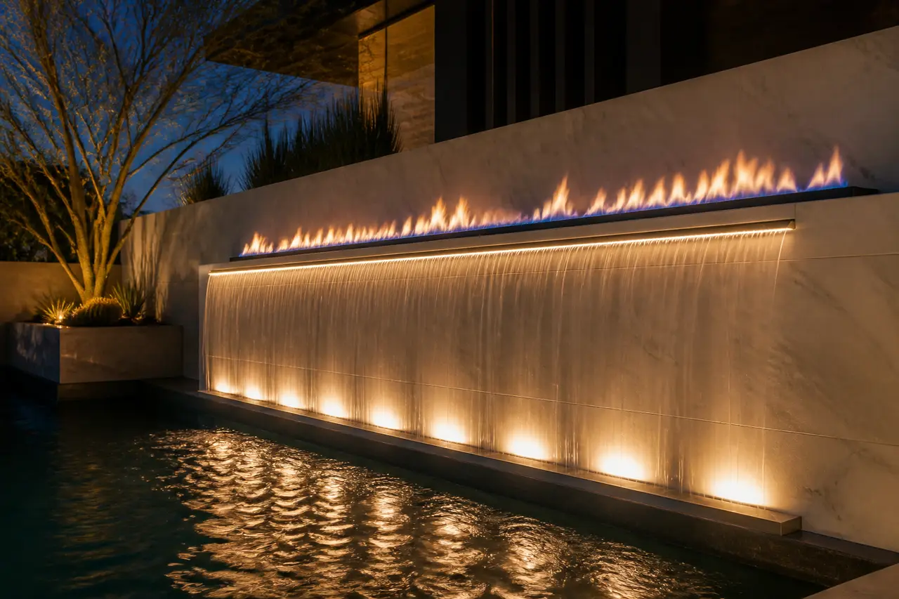
Architectural wall with linear fire above a falling water sheet.
- Size range
- 8'-14' wide, 8'-10' tall (planning range)
- Installed investment range
- $28,000 – $58,000
- Best for
- Pool focal walls, modern courtyards, signature features
Two pages: concept rendering, planning dimensions, option decisions, and verification checklist. No email required.
Start with this conceptAn illustrated starting point
This concept is not a permit, engineering, fabrication, appliance-cutout, code-approval, or construction drawing. Field measurements, selected manufacturer documents and listings, site and utility conditions, required qualified engineering, AHJ/HOA review, approved documents, and the signed scope control the final design. The installed investment range is for planning, not a quote.
About this design
Architectural wall carrying two systems at once — a listed linear gas appliance along the top and a sheet-flow spill down the face into the water below. Both systems need their own routing, controls and shutoff, coordinated inside one structure.
Key features
- · Listed linear gas appliance along the top
- · Sheet-flow stainless weir below
- · Tile, stone, or porcelain face
- · LED lighting planned for serviceable access
- · Independent control and shutoff for each system
Equipment & systems
- · Listed linear burner from a current selection family, sized in the approved design
- · Listed gas valve and ignition selected with the appliance
- · Variable-speed water pump selected in the approved design
- · Underwater and wash lighting selected for serviceable access
- · Control integration where the selected equipment supports it
How this fire feature is planned
One architectural wall carries two systems at once — a linear listed gas appliance along the top and a water spill down the face into the water or catchment below — with the fuel, water, electrical and service routes all reserved inside a single structure.
A signature focal wall. Because two systems share one face, the wall proportions and the face material do more work here than on any other concept.
Flame above moving water, usually viewed from across a pool rather than approached. It is a composed nighttime picture more than a gathering spot.
Two systems means two sets of requirements. The gas appliance follows its own current manufacturer instructions and the qualified gas trade; the water side follows the approved design, the selected equipment and the qualified electrical trade for circuits and bonding. Controls are coordinated so both can be shut down independently.
Hard water leaves mineral film where water meets a fire element, so the interface detail and reachable access to both systems are planned before the wall is finished.
Zones this concept reserves
- AFire trough line
The listed linear appliance and its media along the top of the wall
- BWall face and spill
The finished face the water travels and the release edge below the fire line
- CReceiving water and return
The pool or catchment below and the return path back to the water system
- DWall structure and substrate
The structure carrying both systems and all concealed routing
- EFuel, power, controls and service
Reserved gas, water, electrical and control routes with independent shutoffs and real access
Finish and material zones
- Wall face material
- Porcelain, tile or stone — evaluate for mineral staining from the water and for soot and heat above.
- Fire trough trim
- The visible metal at the top of the wall and how it weathers in sun and splash.
- Release and cap detail
- The edge the water leaves from and the cap between the two systems.
- Lighting treatment
- How the water and face are lit at night, and whether fixtures can be serviced without demolition.
Lock these before fabrication and ordering
- Overall concept envelope — wall width and height as a planning range, field verified
- Face material and how it will look with both mineral film and heat above
- Where the wall sits relative to the primary indoor and seating view
- Whether fire and water are used together, separately or on independent controls
- Lighting approach and reachable fixture service
- Equipment and shutoff locations, screening and access clearance
Verified before anything is built
- The selected current manufacturer instructions and listing for every burner, insert, valve, ignition and control — obtained and reviewed before fabrication or ordering
- Clearances, enclosure and combustible-material requirements — taken from the selected listed appliance's own instructions, never from a general rule
- Wall structure, substrate and waterproofing for the approved detail, with qualified engineering where required
- Fuel type, routing, sizing, pressure, shutoff location and total connected load — determined by the qualified gas trade for this address and this scope
- Circuits, controls, bonding and any low-voltage work — determined by the qualified electrical trade and the approved documents
- Current AHJ and HOA requirements for this address and this scope — confirmed in writing before construction
Living with it — care and seasonal notes
- Expect mineral film on the face and at the release edge; cleaning frequency follows your water.
- Keep both systems independently reachable — gas components and water equipment rarely need service at the same time.
- Plan a top-off and shutdown routine for the water side during service or extended absence.
Planning this feature in Arizona
- Hard water marks a dark or polished face quickly; the face finish decides how visible that is.
- Wind carries a thin sheet sideways and affects the flame above; orientation is evaluated for both systems on site.
- Summer heat and dry air increase water loss, and blown dust settles in the catchment — both change the maintenance rhythm.
This planning board is a concept-stage tool. It is not permit, engineering, fuel or gas, electrical, structural, venting, manufacturer-installation, code-approval, safety-inspection, or construction documentation, and nothing here is an installation instruction. Selected current manufacturer instructions and listings, qualified gas, electrical and structural trades as applicable, measured site conditions, total connected load, current AHJ and HOA requirements, approved documents, and the signed scope control the final build. Never leave a burning fire feature unattended, and keep children and pets supervised around it.